A series of printed circuit boards [PCBs] weave a narrative from the fundamentals of electronics, to the transistor, logic gates, computational building blocks to a programmable micro-controller.
\n\n
A series of \"physical lecture notes\" present a low level entry point into the material of electronics. This perspective is usually reserved for engineers, and obfuscated within the sealed boxes of our phones and computers. Here we consider the material of computation as just physical stuff, where the base material unit is the transistor and we build up from there.\n
This piece was originally developed in 2020 to support the Poetic Hardware curriculum at SFPC, a course which supports artists in their use of technology as a tool within a creative practice. It is now in its 3rd iteration.
\n\n
With PCB 01, we introduce the anatomy of a PCB, practice soldering surface mount and through hole components, edit PCB traces with a utility blade and learn continuity with a multimeter.
The lower part is a snap-off power supply module that offers different ways of powering projects. And finally in the middle portion are several basic LED, resistor and switch circuits.
\n\n
PCB 02 presents the electronic switch. Here we play with a relay as an electronically controlled switch and signal amplifier, and then also introduce the N-MOS and P-MOS transistor as a version of the electromechanical relay as a solid-state device (with no moving parts). From here we use CMOS (complementary metal oxide semiconductor) logic, to build logic gates from transistors. These are the fundamental building blocks of all functional computers and CMOS logic is the logic family in use today.
\n\n
PCB 03 is the first step into encapsulating the transistor. We begin the process of encapsulation as the transistors which form NAND logic gates are neatly packed into the 4093 integrated circuit (IC). We choose the NAND gate because it is one of the universal logic gates, from it you can create all other logic gates. From here we use NAND gates to build an inverter, AND and XOR gate and then wire them as a half-adder, illustrating first stage in a functional binary calculator.
\n\n
PBC 04 introduces feedback + memory. Here we explore what happens when we connect the output to the input of a logic gate. All of a sudden the present state of a circuit, depends not on the state of its inputs, but on its previous state. We begin considering circuits as time-based.
The first circuit at the top clocked 1-bit memory circuit made from a d flip-flop. This one's a personal favorite and inspired 1bit 1hz cpu, from way back. The middle circuit wires the d flip-flop as a binary counter, which is also a divide-by-2 circuit. The last circuit uses a 4013 IC as a decade counter.
\n\n
PCB 05 is all about time. Again using feedback to build oscillating circuits. Here we have a relay oscillator, where oscillation speed is limited by a physical mechanism. The middle row has a series of schmitt-trigger inverter oscillators. These oscillations are visualized both visually and aurally. The intention was to keep the oscillations within a scale most can perceive with un-augmented senses. And finally a 555-timer circuit set around the 1hz frequency.
\n\n
PCB 06 is a circuit of a barebones arduino. The idea behind this is to show the necessary components to incorporate a programmable microcontroller in a project. It is helpful as a jumping off point for those wanting to build their own microcontrollers and who are unsure where to start.
\n\n\n\n\n
1bit memory.\n The input [lower indicator LED/switch] gets registered to an output [upper indicator LED] only on the low->high clock [left side switch] transition.
For a chance to get this jump rope, please send us a receipt of $10 or more to the following organizations by June 14, 2020. Every $10 gets you one lottery ticket. We will then pick 5 winners at random.
For a chance to get this jump rope, please send us a receipt of $10 or more to the following organizations by June 14, 2020. Every $10 gets you one lottery ticket. We will then pick 5 winners at random.
This project is a Prerelease. Objective: Make your own currency.
\n
\n
Release 04/12/2016: Nothing Lasts Forever
\n
Glass, Aluminum, Custom PCB, E-Ink Display, AA Battery
\n
ø30mm x 100mm
\n
Limited Edition of 999,999
\n \n
Each press of the button increments the counter by one. If and when the counter reaches 999999, the devices stops functioning.
\n
\n
\n
Each device is engraved with its edition number.
\n\n
\n
Electrical and mechanical components and their associated minimum lifecycle:
\n
\n
-The e-ink display has a working lifespan of about 50,000 hours, which translates to about 90,000,000 refreshes at 2 seconds each.
\n
\n
-While the button is not engaged, the electronic circuit shuts down completely. In order for the microchip to power down without losing count, each time it powers down, the current count is recorded to EEPROM.EEPROM is volatile memory, so it rated to be written into at least 100,000 times for each byte. Since we’re storing 6 digits, we have the luxury of spreading the 6 digits across 4000 bytes. So a 6 digit number can comfortably be written into EEPROM 66,000,000 times.
\n
\n
\n
\n
-Power is only consumed while refreshing the e-ink display. With a AA battery, the device can refresh approximately 80,000 times.The count is written into memory each time it powers down so the battery can be changed without disrupting the count.
\n
\n
-The momentary push button is rated to for a minimum of 1,000,000 cycles at 50N, which is well above the 2.5N that is required to activate the switch.
\n
\n
-This device is guaranteed to function until the counter reaches 999999. It is also guaranteed to stop functioning once the counter has reached 999999.
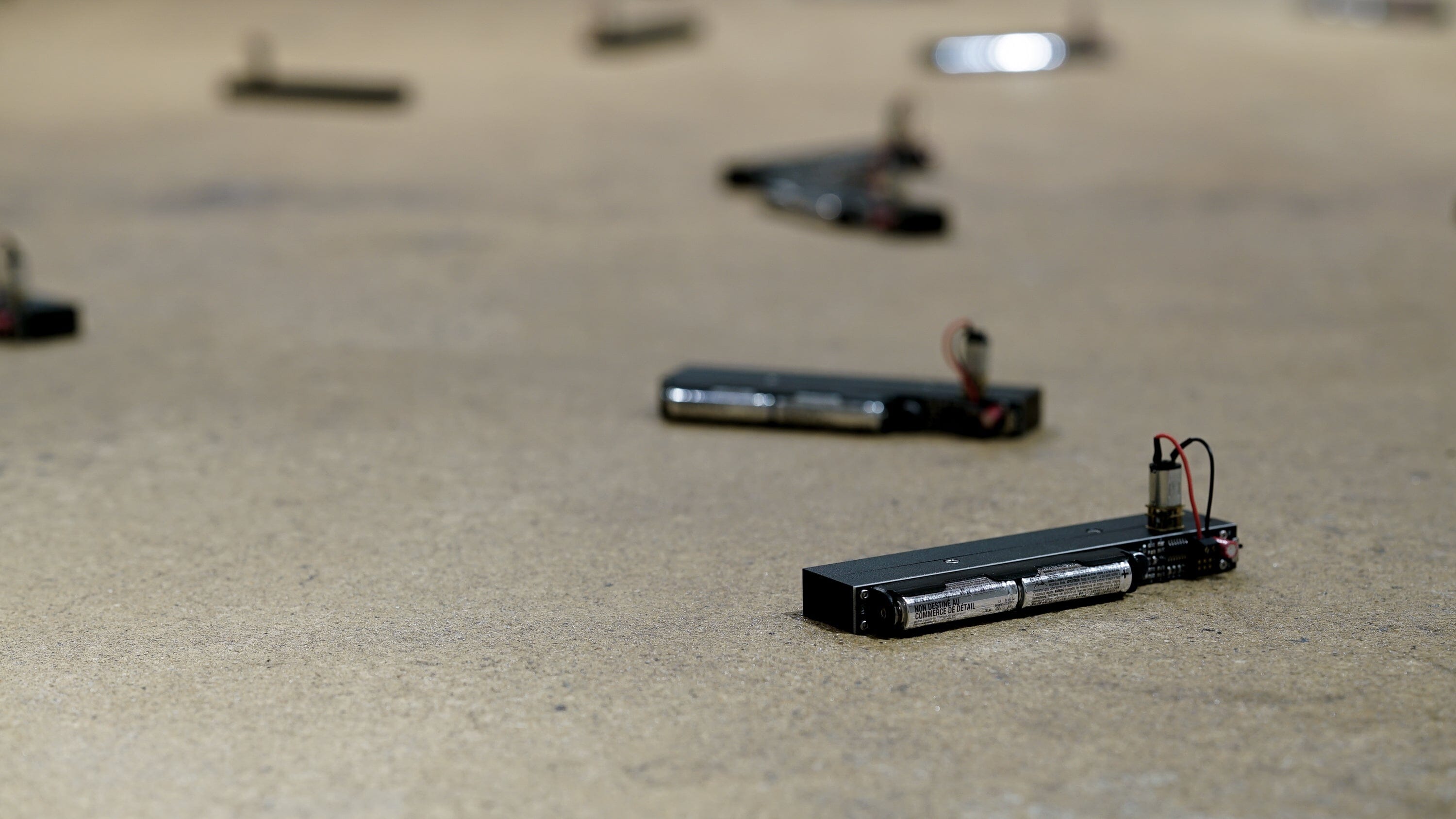
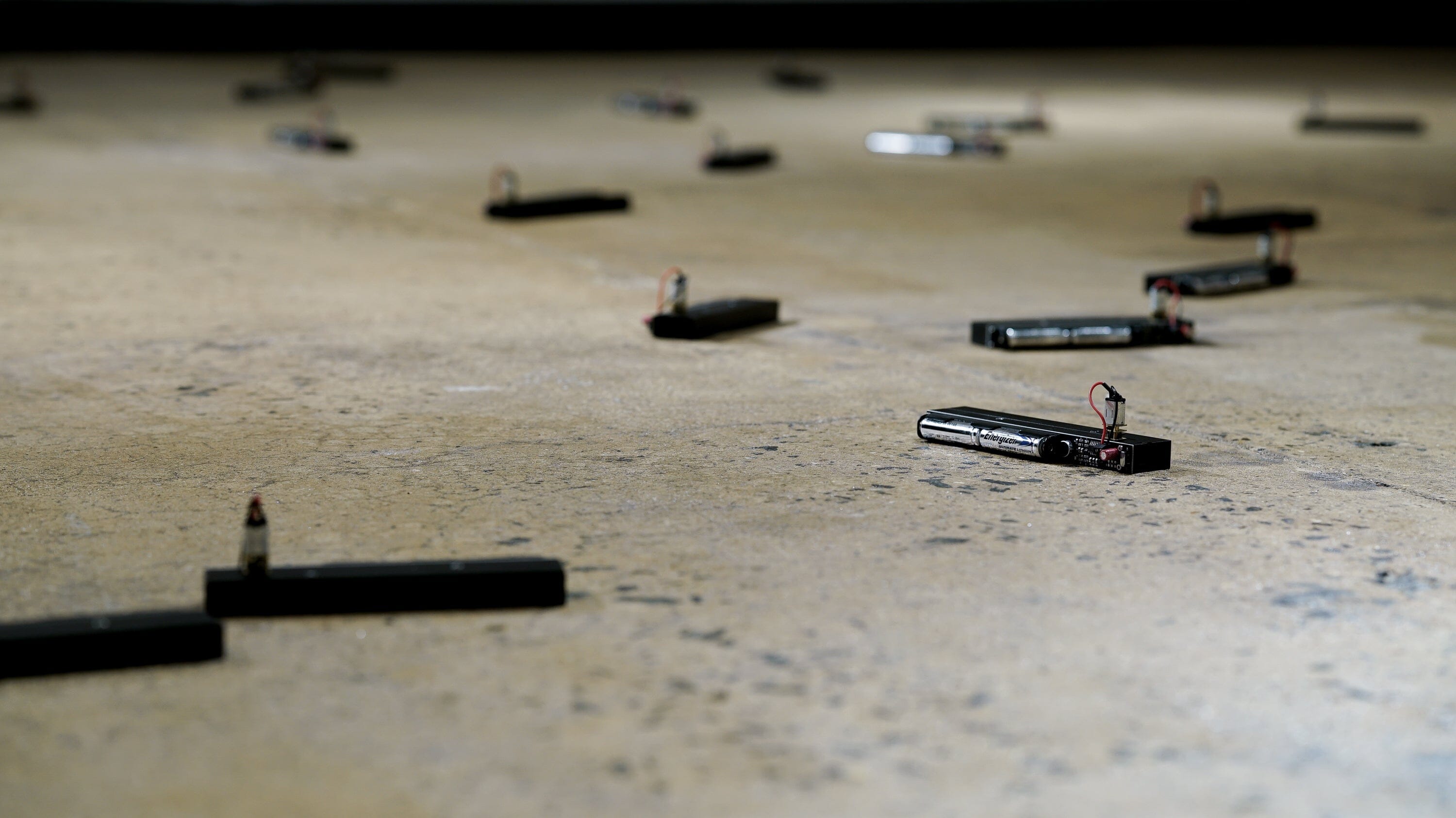
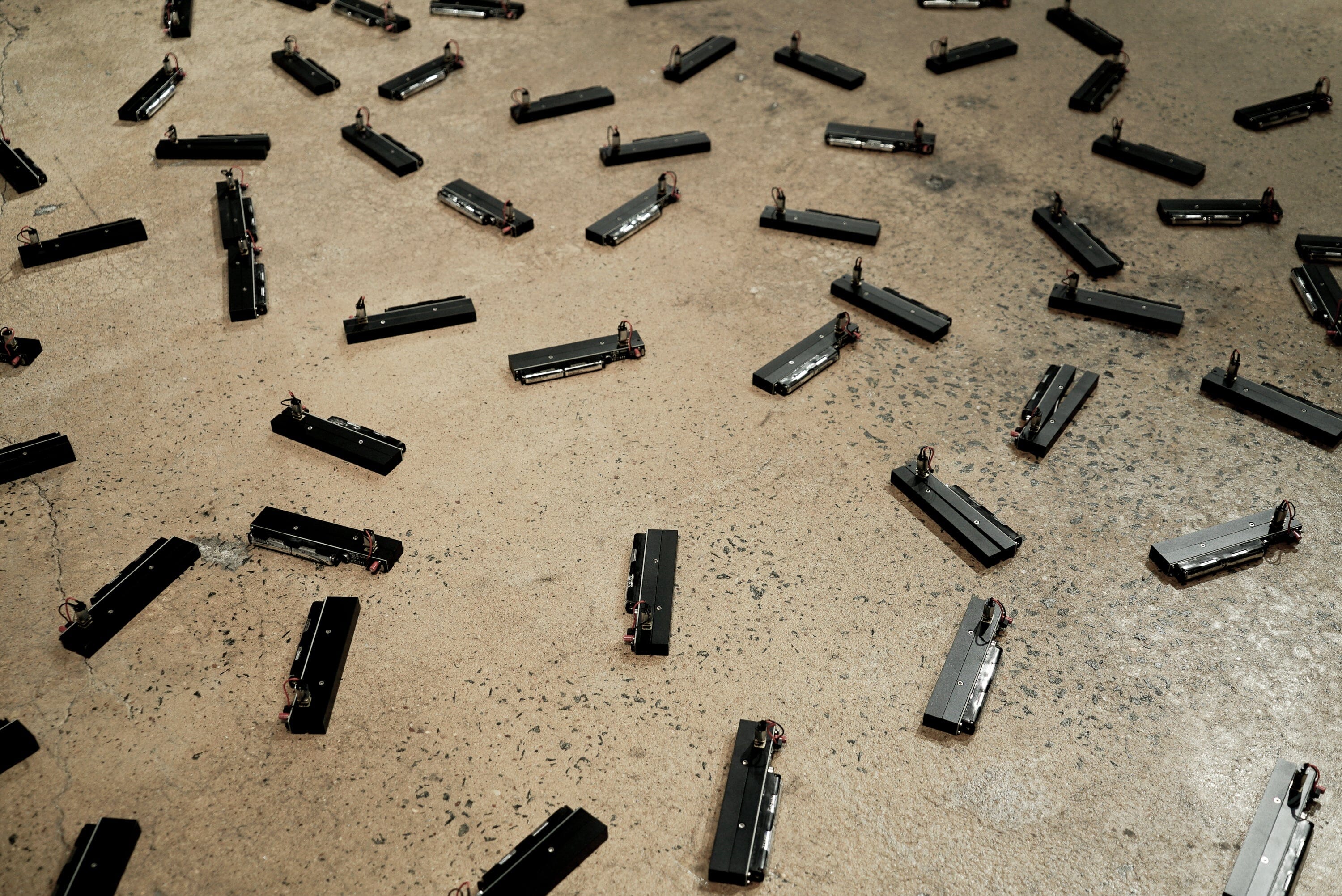
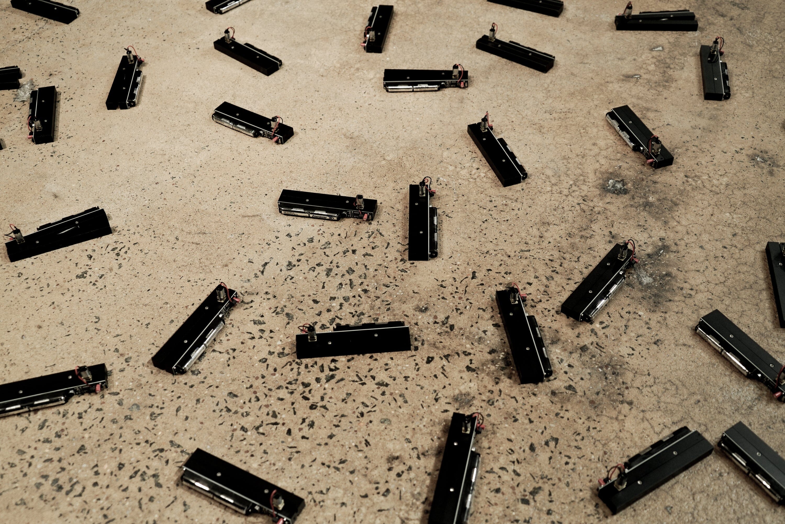
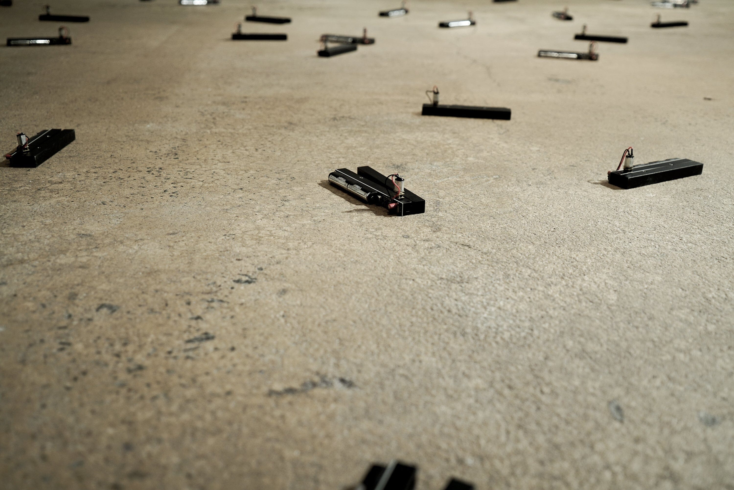
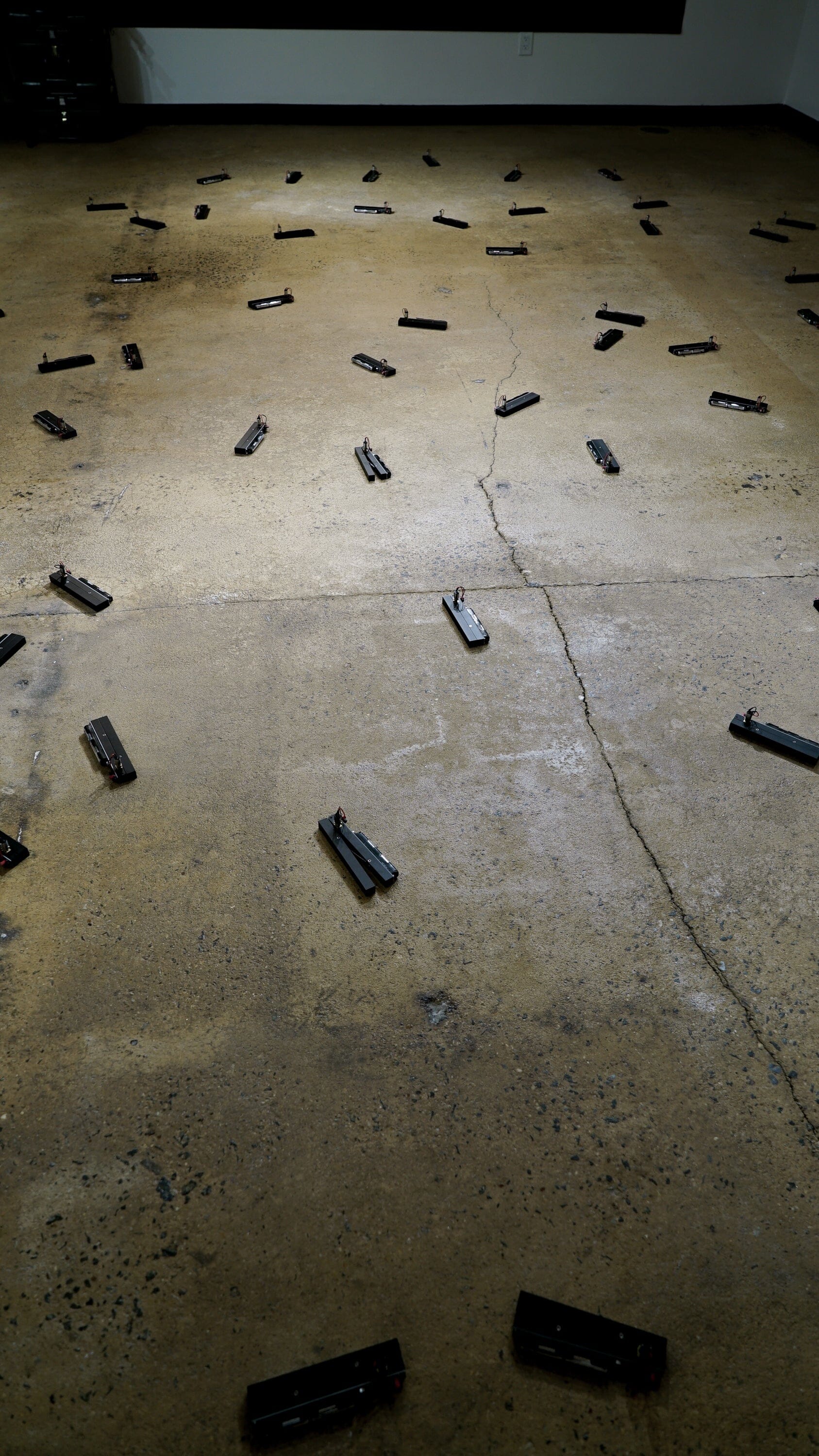
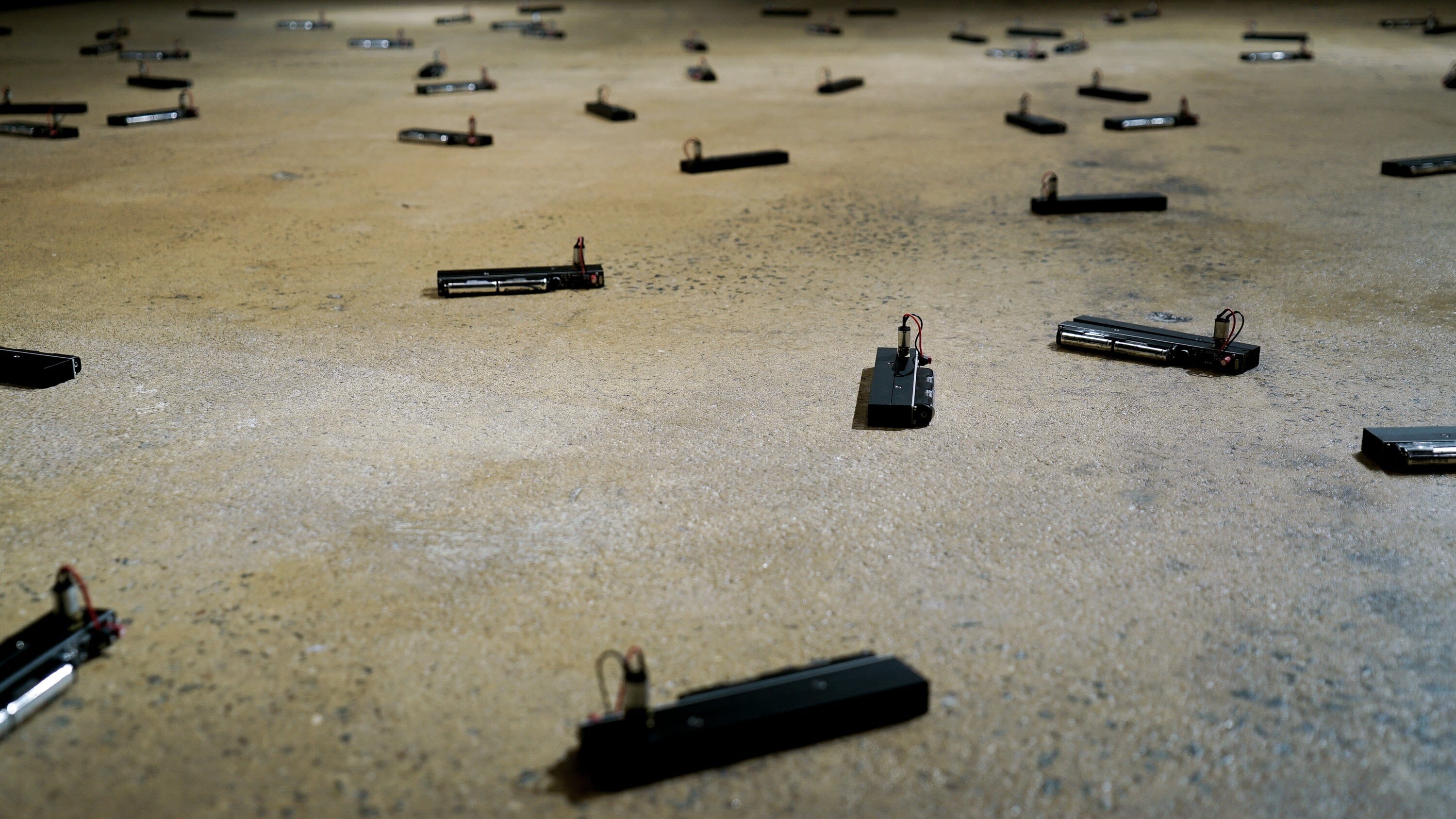
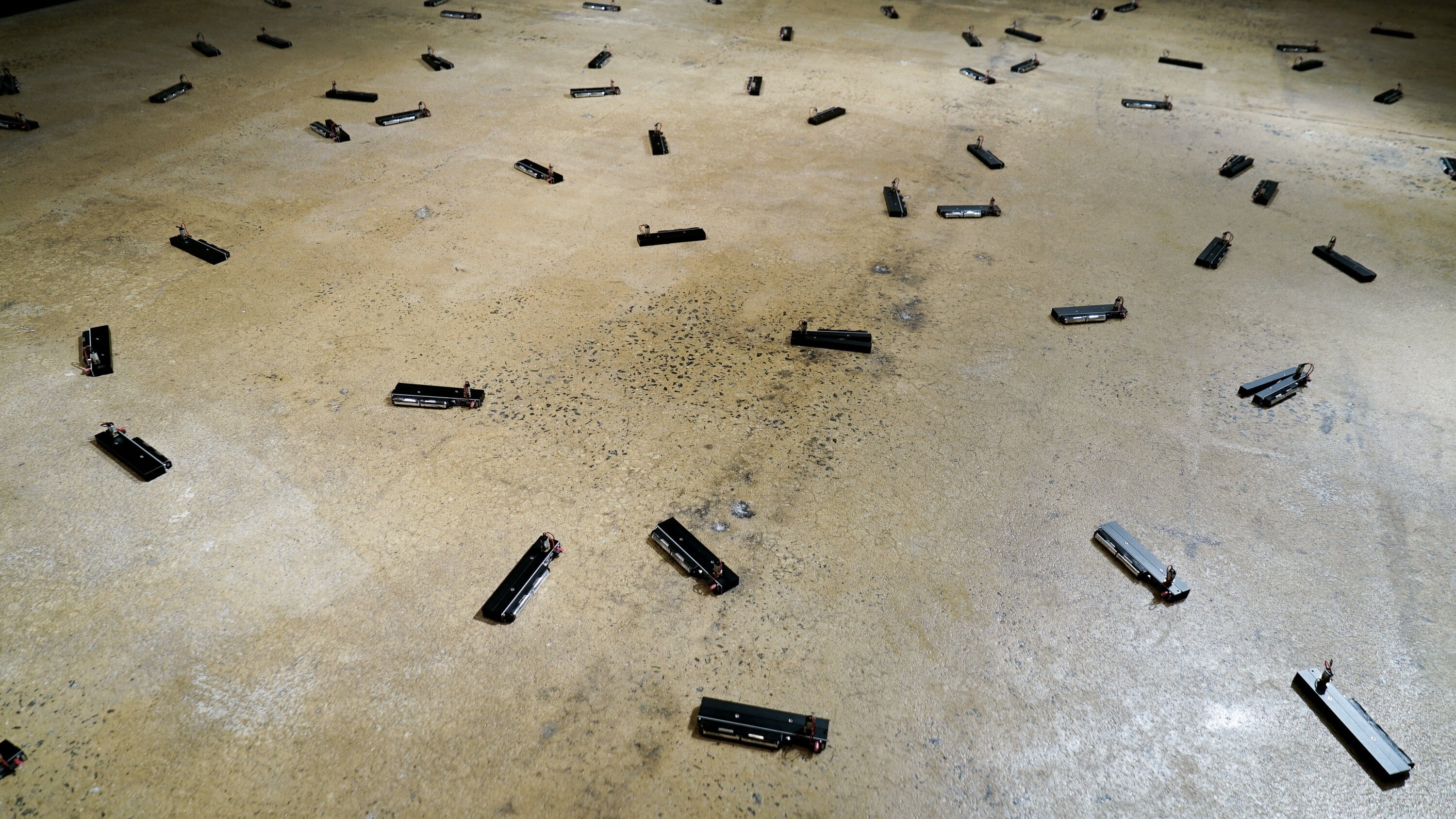
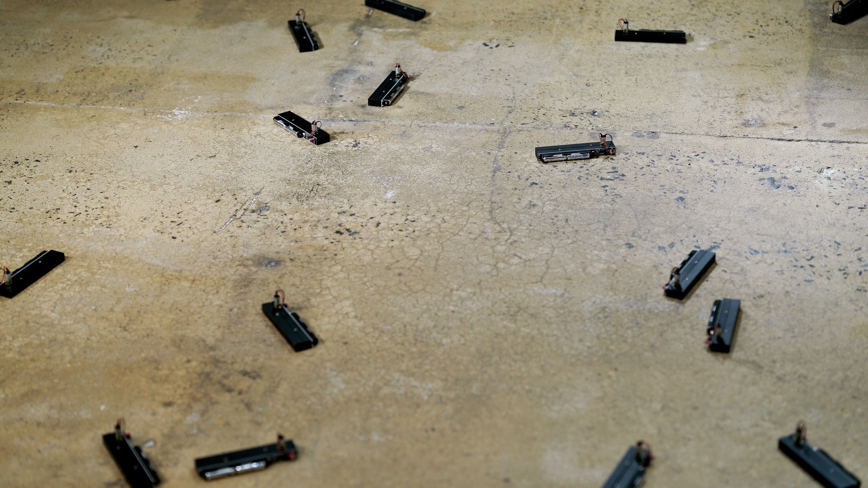
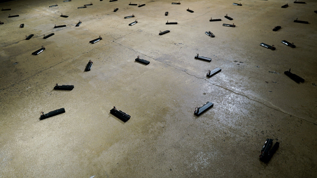
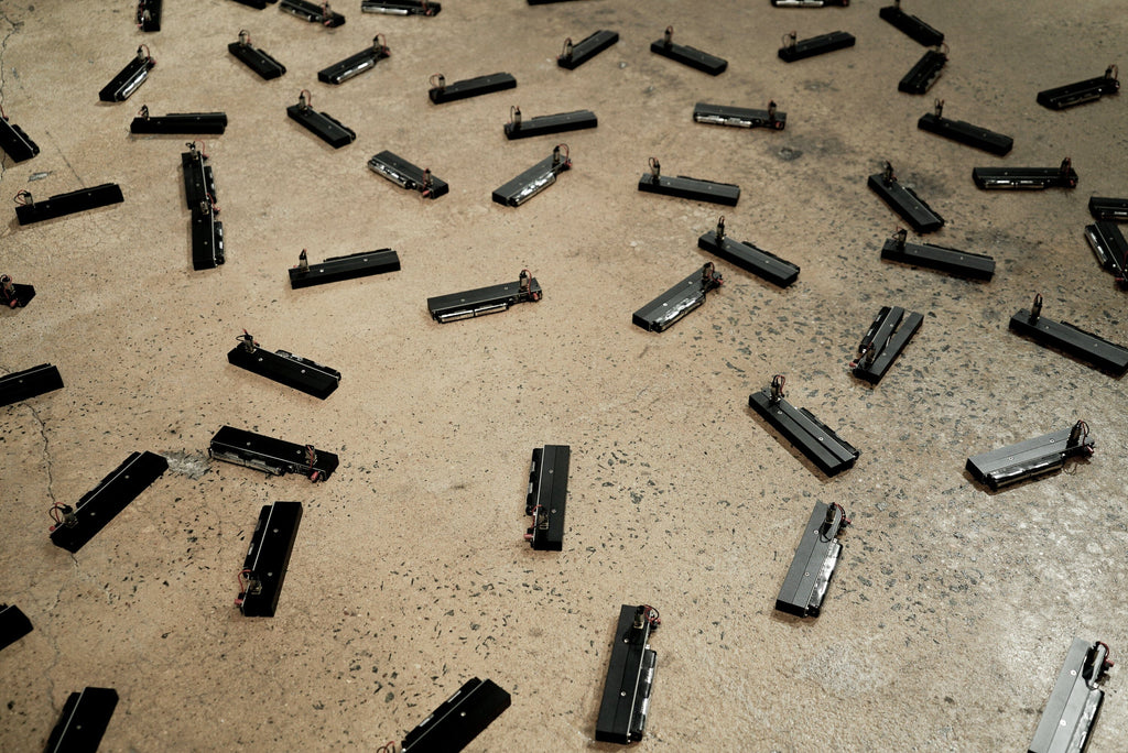
100 Clapping Machines is an indoor installation of a hundred individual clapping machines, sometimes clapping in unison, sometimes seemingly randomly. Visitors are encouraged to interact with the installation by making sounds (clapping or stomping).
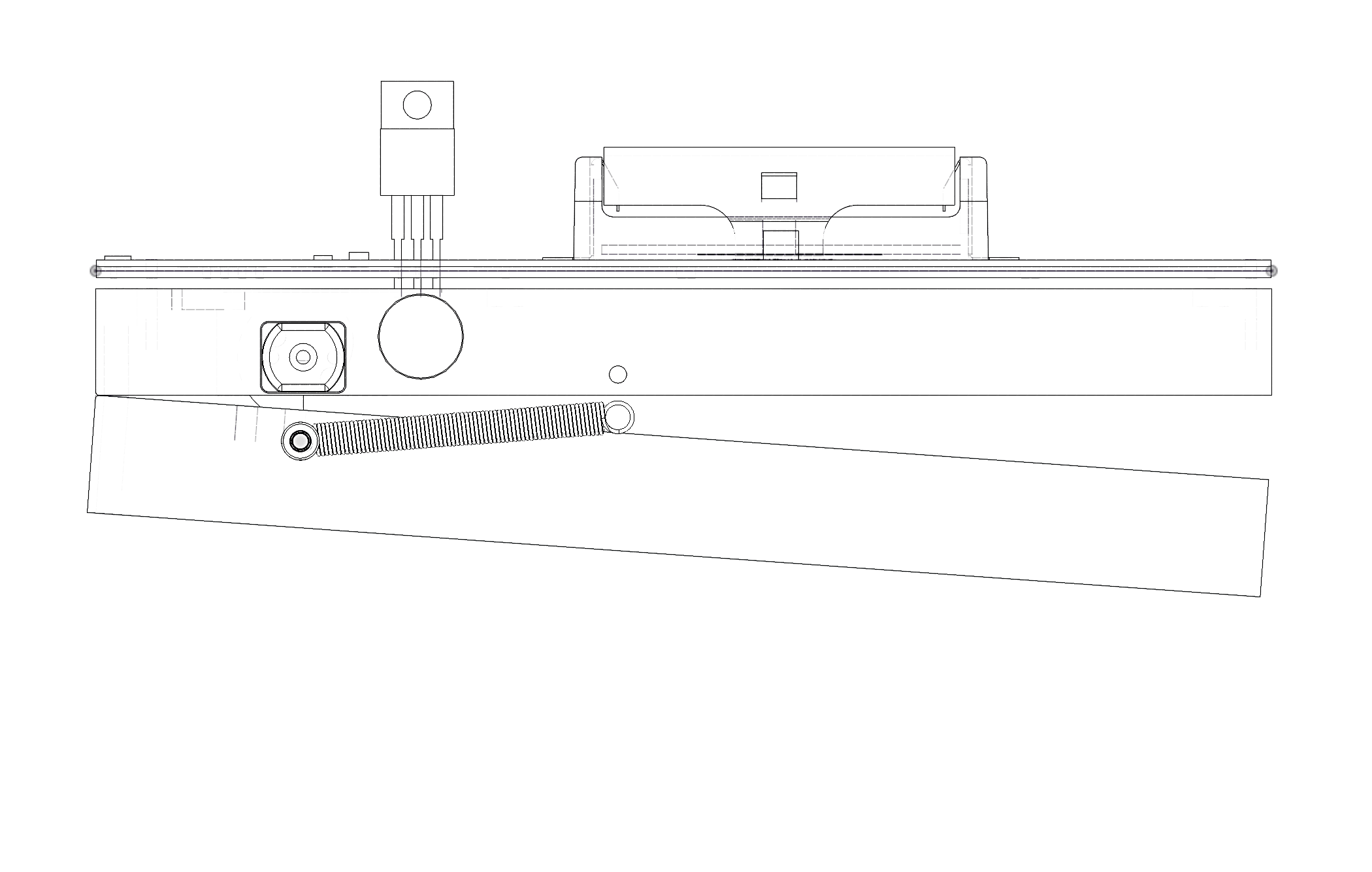
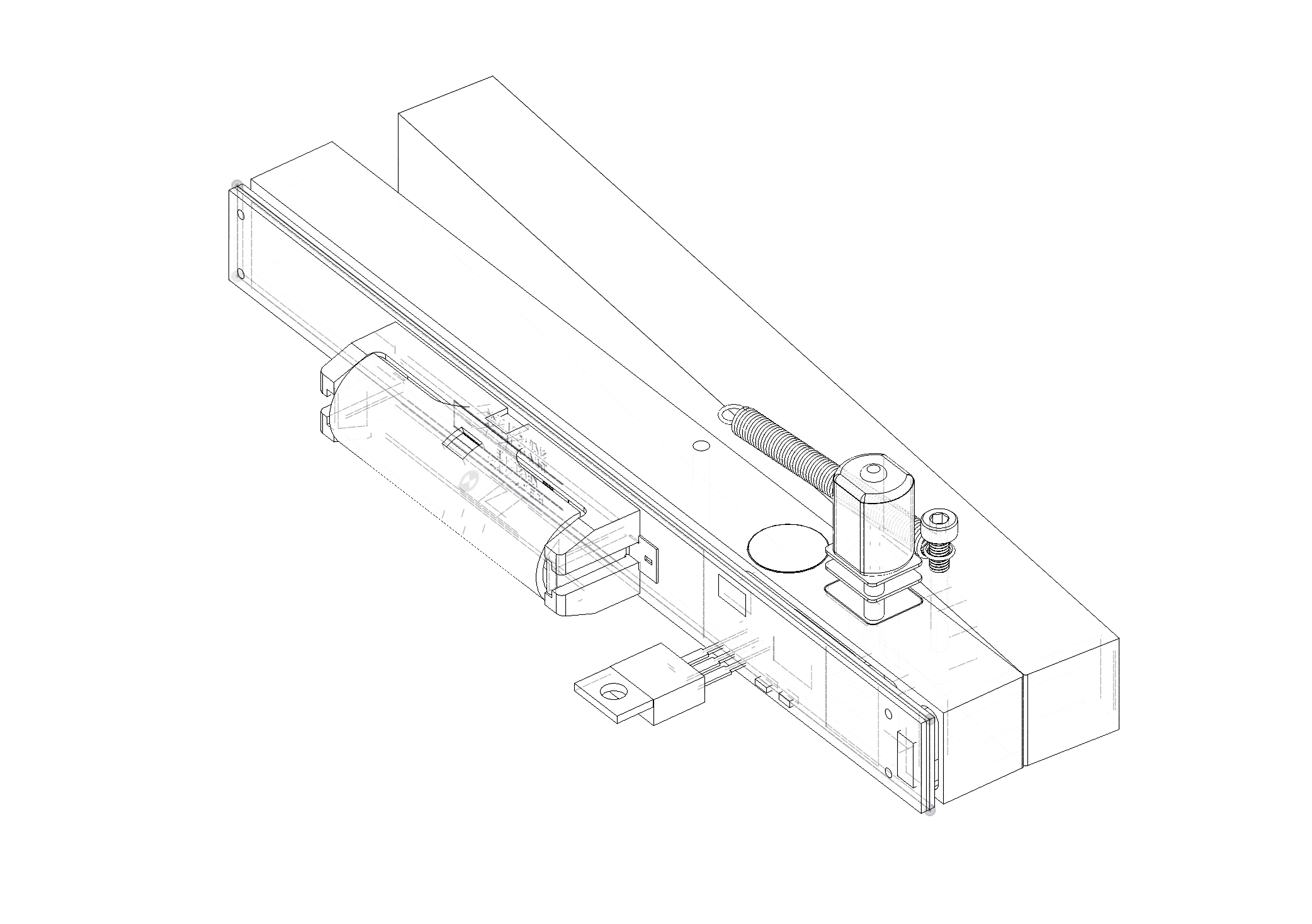
Each clapper claps on a time interval, but will also adjust its phase (i.e. time delay) as it listens to match its neighbors' claps, similar to how some species of fireflies synchronize their flashing. Each clapper has a small microcontroller, a piezo (acting as a microphone), a motor with a cam, and a spring to actuate two blocks of aluminum that hit each other to clap.
This project highlights the beauty of and the science of sync. As visitors walk around the installation and disrupt the synchronization of clappers they can see how syncing works and how we can become part of it or become disruptions in the system.
This exhibit was created in collaboration with Helio Takai, and is sponsored by Pratt Institute's STEAMplant Initiative, with additional reception support by the Academic Senate.
Through the installation, visitors from the Pratt community and beyond were able to learn about the science of synchronization and interact with the clappers. Some people sat quietly observing the clapping, others stomped their way through the machines, creating disruptions in the synchronized clapping.
The biggest challenge encountered during the project was developing a robust mechanism and sensing circuit that worked together so each clapper behaved predictably, yet when grouped together, unpredictable behaviors emerged.
With 5-10 clappers in a space, they would synchronize, but in larger groups of 70 or more, the clappers would form clusters of sync, causing them to go in and out of phase. Each clapper is more sensitive to sounds on one side due to the position of the mic on each clapper.
Clappers over time would also rotate and move across the floor, causing even more unpredictable phases of sync.
The the generous support of STEAMplant, we were able to cover the majority of the fabrication costs for the machined metal parts and the electronics.
The clappers were designed and prototyped by Che-Wei Wang with help from Taylor Levy. Helio Takai provided consultation for the design. Josh Levine rewrote the firmware to make the clappers actually work. Colin Lysik assembled clappers.
Choosing a selection results in a full page refresh.
 \n
\n \n
\n \n
\n \n
\n \n
\n \n
\n \n
\n \n
\n


 \n
\n